The Use of a Control Drawing for an Intrinsically Safe System
The Role of a Control Drawing
A Control Drawing plays an important role in the safe installation, operation, and maintenance of an intrinsically safe system. It is typically a block diagram created by the manufacturer or system designer to outline the components of the intrinsically safe system and their parameters – in sufficient detail as to ensure a safe installation of the Field Device in a defined, hazardous environment. The drawing conveys what makes the electrical circuit represented intrinsically safe.
Such safety is of critical importance given that the system is installed where fire or explosion hazards may exist due to the presence of flammable gases or vapors, flammable liquids, combustible dust, or ignitable fibers or flyings – a hazardous (Ex) environment.
Responsibility for the safety of the intrinsically safe system goes beyond its design! Intrinsically safe circuits must be installed and maintained according to the Control Drawing. Control Drawings show each part of the system and their interconnectedness and show that the assembly will be safe if installed as indicated on the drawing. Control Drawings must therefore be kept on location wherever an intrinsically safe system is installed. These records should be accessible upon request by installers, inspectors, as well as by operations, safety, and maintenance personnel.
Before we explore what makes up a Control Drawing, let’s review the basics of the intrinsically safe protection technique used in hazardous locations.
What Makes an Electrical Circuit Intrinsically Safe?
Intrinsic safety (IS) is a system concept: each IS assembly includes three main, interconnected components:
- An intrinsically safe Field Device (known as the IS device)
- A Safety Barrier (also known as the associated apparatus), which is an energy limiting device
- Intrinsically safe field wiring which connects the Safety Barrier to the Field Device
Intrinsically Safe Field Device
The Field Device is a device situated within a hazardous location, which must be protected from any source of energy that can cause ignition of a mixture of flammable or combustible material in air. Intrinsic safety is the protection technique used to prevent sparks or thermal effect from causing a fire or explosion in such a classified hazardous location.
Safety Barrier
The Safety Barrier is a device that limits the energy that may travel to the Field Device within the hazardous area under fault conditions. Current and voltage surges are kept by this protection technique from turning an electrical device into an ignition source, even in the case of failure.
The Safety Barrier is normally located within an unclassified (not a hazardous) location. It may also be installed in a hazardous area, but needs additional protection techniques, depending on in which classified area it is installed.
The Safety Barrier must be certified as suitable for use in the IS system, given the defined hazardous location, the nature of the hazard (gas, dust), the classified area, its ambient temperature, and so on.
Intrinsically Safe Field Wiring
Intrinsically safe field wiring is the interconnecting cable between the Safety Barrier and the IS device. This wiring must be installed as per the relevant regulation.
For installation in Canada, field wiring must comply with CE Code (CEC) Rules 18-064 and Appendix F for intrinsically safe installations. In the US, compliance is required with NEC 504.
What Information is Indicated on a Control Drawing?
A Control Drawing details the nature of components in both the unclassified location and the classified location in which the IS system is located, as well as the cables that connect the two locations.
a. The Safety Barrier in the Unclassified Location
Details about the Safety Barrier (located in the unclassified side of the system) and identified on the Control Drawing and include these:
- The name of the manufacturer
- The model number
- The certificate number
- The Ex marking
- Grounding details
- The maximum voltage that enters the barrier (known as Um) from the power supply*
- The maximum output current (Io)*
- The maximum output voltage (Vo)*
- Maximum power (Po)*
- Maximum inductance that can be connected to the Safety Barrier (Lo)*
- Maximum permitted capacitance that can be connected to the Safety Barrier (Co)*
- The maximum value of the ratio of inductance to resistance that may be connected to the Safety Barrier (Lo/Ro)*
Note: *These are referred to as “entity parameters”.
b. The Cables that Connect the Safety Barrier to the Field Device
Details are provided on the Control Drawing about the cables that connect the two sides: the unclassified and the hazardous side of the system. The length of the cables that connect the Safety Barrier to the Field Device affect the amount of spark energy as a result of stored capacitance and/or inductance of the cables. Maximum Cable length must therefore be specified and included in spark energy calculations.
For a safe installation, the total capacitance of the intrinsically safe Field Device and the cable must be equal to or less than the maximum permitted capacitance of the Safety Barrier. This is also true for the inductance values of the cables and the IS device.
c. The Classified Location (the Hazardous Location)
Critical details about the following are defined on the Control Drawing:
- The Field Device(s)
- The hazardous location in which the Field Device is located
Field Device
- The name of the manufacturer
- The model number
- The certificate number
- The Ex marking
- Grounding details
- Vi – the maximum voltage (peak AC or DC) that can be applied to the connection facilities of the apparatus without invalidating the type of protection*
- Ii – the maximum current (peak AC or DC) that can be applied to the connection facilities of the IS device without invalidating intrinsic safety*
- Pi – the maximum power that can be applied to the connection facilities of the IS Device*
- Ci – the total equivalent internal capacitance of the apparatus that is considered as appearing across the connection facilities of the IS Device*
- Li – the total equivalent internal inductance of the apparatus that is considered as appearing across the connection facilities of the IS Device*
Note: * These are called the “entity parameters” of the Field Device.
The Hazardous Location
The following are indicated on the Control Drawing:
- The classified area – the Class, Division or Zone
- The explosive material Group (Dust and/or Gas group)
- Ambient temperature
- Temperature class
How does the Control Drawing Help with the Installation of an Intrinsically Safe System?
The CE Code and NEC require that the manufacturer provide descriptive documents for an intrinsically safe installation in which the items of electrical apparatus, their electrical parameters, and the electrical parameters of the interconnecting wiring are specified.
The Control Drawing must illustrate that the following values meet the requirements of an intrinsically safe system:
- Uo (the output voltage of the Safety Barrier) must be less than or equal to the input voltage of the Field Device
- Io (the output current of the Safety Barrier) must be less than or equal to the input current of the Field Device
- Po (the output power of the Safety Barrier) must be less than or equal to the input power of the Field Device
- Co (the maximum permitted connected capacitance of the Safety Barrier) must be greater than or equal to the total capacitance of the Field Device and the cables
- Lo (the maximum permitted connected inductance of the Safety Barrier) must be greater than or equal to the total inductance value of the Field Device and the cables
The explosive Gas/Dust Group subgroup must be acceptable:
- For the Zone system of classification: Group IIC, or IIB or IIA as applicable
- For the Division system of classification: Groups A, B, C, D or as applicable
The classified area must be acceptable:
- For the Zone system, Zone 0, 1, or 2, as applicable
- For the Division system, Class I, Division 1 or 2, as applicable
The Temperature Class (maximum surface temperature of the equipment installed in the classified area) must be indicated and must be less than the auto-ignition temperature value of the atmosphere present in the classified area.
The ambient temperature range of the intrinsically safe devices must be shown and checked to ensure the device will be installed within its rating.
Using the Template Provided by Hazcon
Hazcon has created a template of a Control Drawing which shows the connection of one Safety Barrier to an intrinsically safe Field Device with all the minimum required information. This template can be used to generate an effective Control Drawing for the purpose of the safe installation of the system and for the creation of a Descriptive System Document (as per the CE Code for installation in Canada and NEC 504 for installation in the US) which includes more details and supporting calculations for the intrinsically safe system.
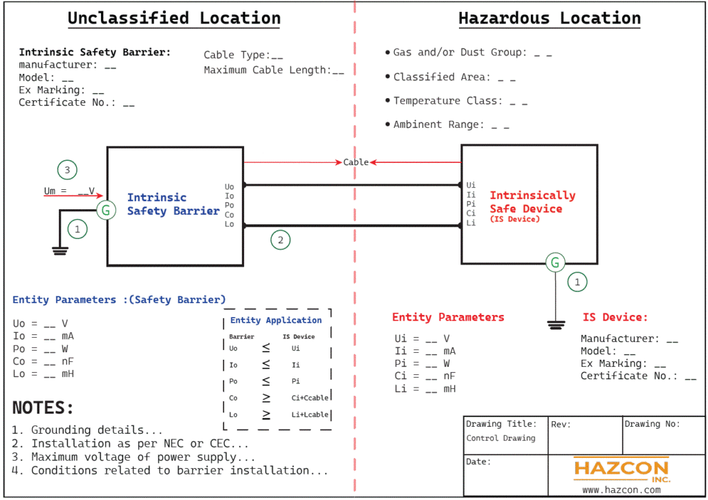
The use of multiple Safety Barriers and IS devices might make the Control Drawing more complex, but in all cases, the Control Drawing must provide clear details about each component and how they are connected.
Request a Consultation
Complete the form below to get started.


